Flight Path Tracker
This project was for my undergraduate dissertiation in year 3. The goal was to capture 3D position information of a moving target, while pointing a laser or camera at it. This involved extensive research, design, building, programming, tuning, and testing. The long term goal is for a derivative of this project to study dragonflies in flight, as they move too fast for a person to keep them in frame. Initially, some already existing systems with similar goals were researched, such as here. From my research, the overall arrangement and mode of operation was decided. A stereo camera pair would be used for 3D position measurements of the target, and a galvanometer mirror pair would be used to point a laser or camera. I ended up using a laser almost exclusively because it was easier to evaluate system performance at the end. Conveniently, a pair of cameras and a laser were already availble, as my supervisor had them already.
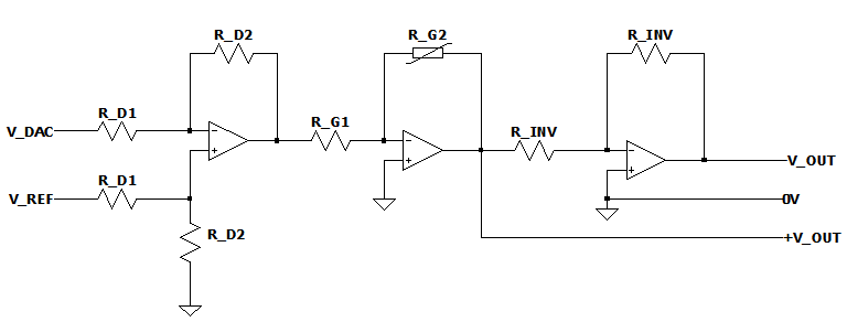
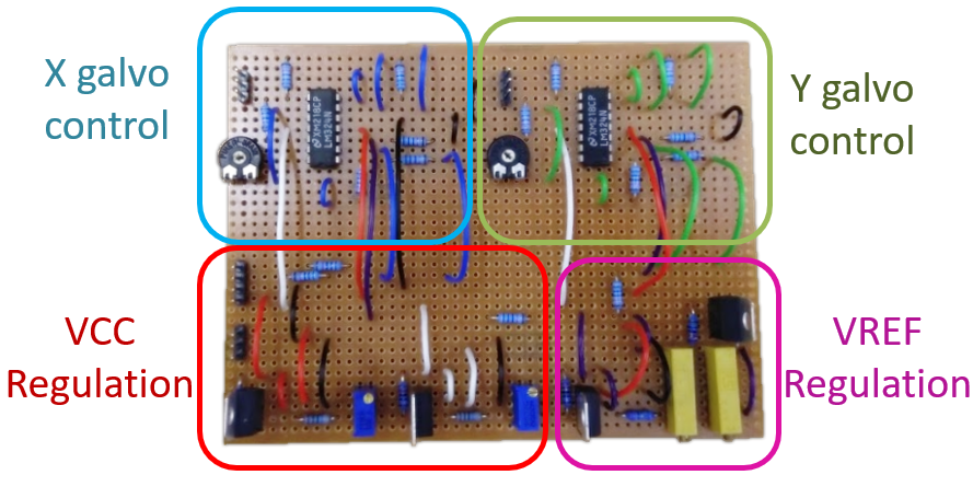
The main challenge with the hardware side of the project was the control of the galvos. Firstly, a galvo kit was purchased from ebay, costing around £50. This contained a power supply, galvo drivers, and the galvos themselves. To control them, the galvo drivers required a bipolar analogue signal. This was done using an Arduino Due and its analogue outputs, with a set of op-amps. The completed circuitry and op amp schematic are shown below. This circuitry maps the analogue output from the arduino to the required range for driving the galvos. The Arduino is to be instructed where to point the galvos based on data from the main control computer, simply using a USB connection.
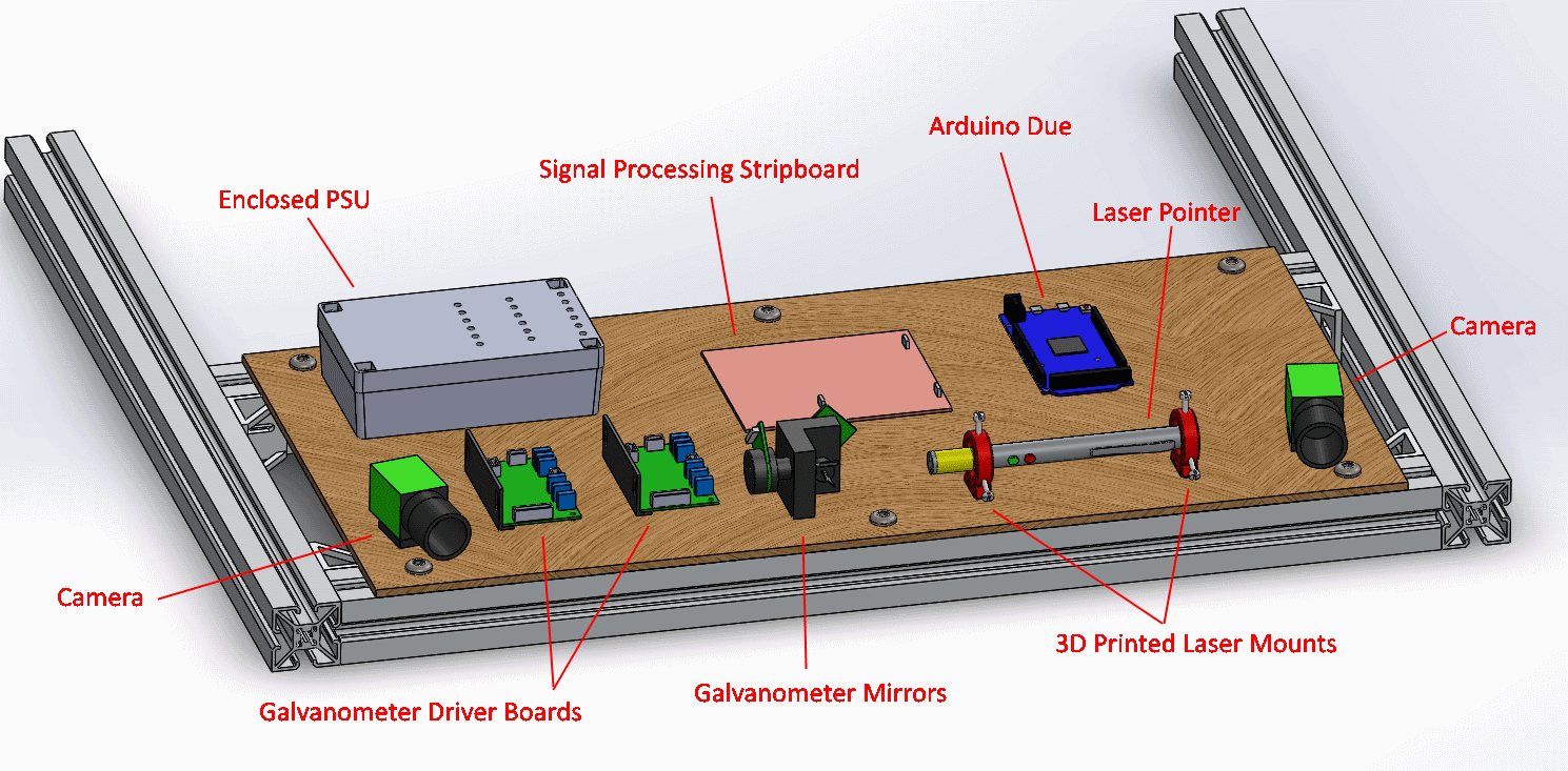
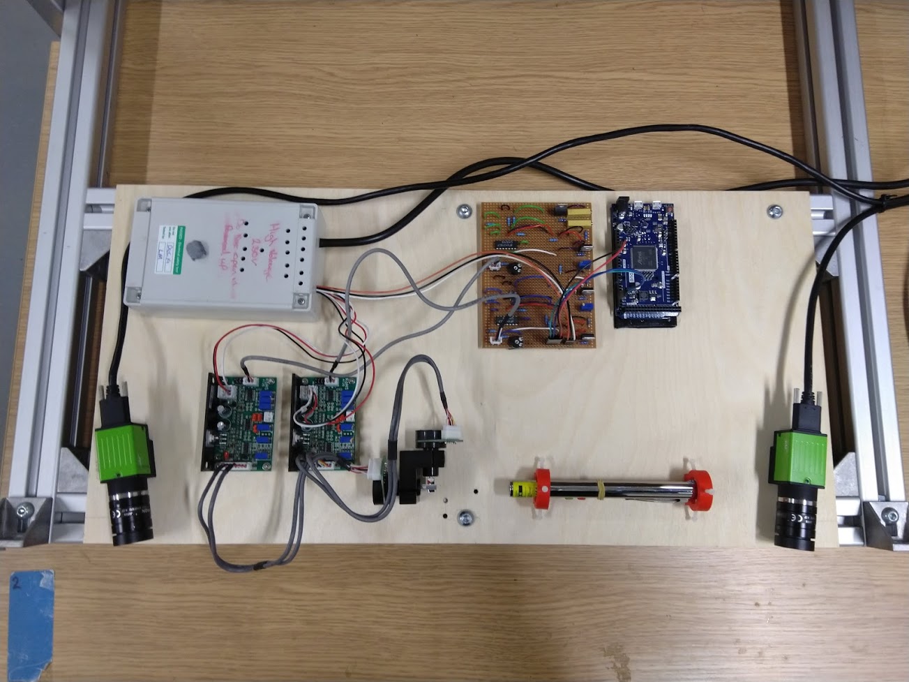
Once the circuitry was confirmed to work, the overall structure was designed and built. The main structure is made of 40x40 aluminium extrusion with a plywood sheet to hold the components.
The hardest and most time consuming part of this project was the software. The main software was written in Python, with the software on the Arduino in C. To make the cameras work in Python, the library Harvesters was used. The libary OpenCV was also used extensively, mainly for camera calibration and identifying the target in each image. The galvos were calibrated by aiming the laser at a grid of points, and then triangulating the 3D position of the laser dot on the wall. From this, a look up table between required angle and galvo input could be generated. Using this information, the laser could then be aimed at the target in real time.
Here is the device tracking a quadcopter (with a big red dot attached because at the time I wasn't aware of how to track more generic objects).
Overall the project was very successful, earning exceptional marks. Note this brief description doesn't give much detail, and simply doesn't put across the amount time and effort that went into this.